



 Scan to BIM
Renovation and retrofit projects carry inherent risks, primarily due to inaccurate or missing as-built documentation. The modern solution is 3D laser scanning, but the raw data—a massive, noisy point cloud—is useless to an architect or engineer until it is translated into an intelligent BIM model.
This translation process requires specialized software, powerful hardware, and a rigorous workflow.
1. Data Acquisition and Registration
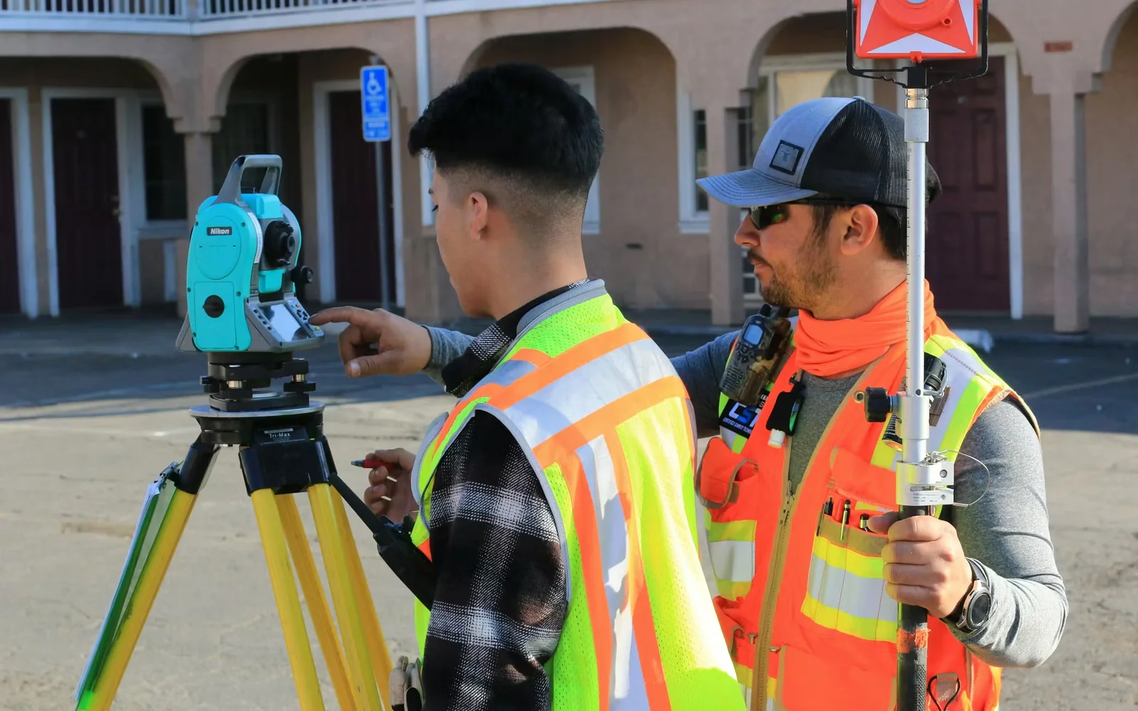
The process begins on site with a terrestrial laser scanner capturing millions of data points. These individual scans are then “registered” or stitched together using software like ReCap Pro to create a single, cohesive point cloud of the entire facility.
The accuracy of the final Revit model is entirely dependent on the quality of this initial registration. Survey control points must be established to ensure the digital model aligns perfectly with real-world coordinates.
2. Defining the Level of Development (LOD) and Tolerances
Before modeling begins, the team must define the required LOD and geometric tolerances.
- Are we modeling just the structural grid and exterior shell?
- Do we need to model sagging beams exactly as they exist, or can we model them orthogonally to represent design intent?
- What is the acceptable deviation between the point cloud and the Revit element (e.g., +/- 15mm)?
Clear communication of these requirements prevents over-modeling (which wastes time) and under-modeling (which creates risk).
3. The Modeling Phase
With the registered point cloud linked into Revit, the modeling begins. Utilizing professional Scan to BIM Services is often the most efficient approach, as it requires modelers trained to decipher complex scan data.
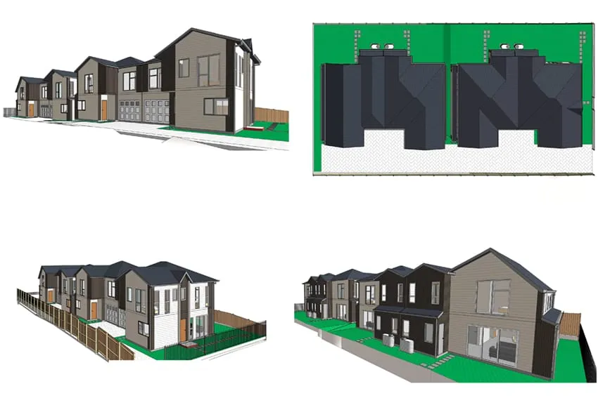
Modelers slice the point cloud using section boxes and trace the existing conditions, prioritizing primary structural elements before moving to architectural features and exposed MEP systems. Custom families may need to be created for historic or non-standard elements that do not exist in standard Revit libraries.
4. Quality Assurance and Clash Verification
The final step is rigorous QA. The completed Revit model is visually inspected against the point cloud to ensure all elements fall within the agreed-upon tolerances. Slices are taken throughout the model to verify that walls, columns, and pipes align perfectly with the laser scan data.
The result is a highly accurate, data-rich existing conditions model that architects and engineers can confidently use as the foundation for their new design.


